# Logic Trees
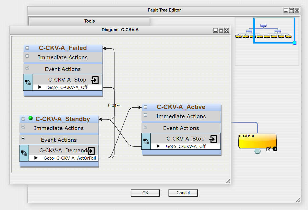
Once components are modeled, a logic tree similar to a Fault Tree from traditional modeling can be constructed. Logic trees allow for complex behavior to be easily modeled. An equivalent model using only Markov type modeling would require exponential growing and complex models. A standard use of Logic trees would be in System diagram models with just two states and a special event used to evaluate Boolean logic. The two states are "Active" and "Failed", with a "Component Logic" event in the active state evaluating the assigned logic whenever a component diagram state changes. If the logic ever evaluates to false, then the current state shifts from "Active" to "Failed". As shown in the System Diagram example in the Types of Diagrams: System section.
The following will give introductions to all the elements seen in the Fault Tree Editor and how to use them to construct a logic tree.
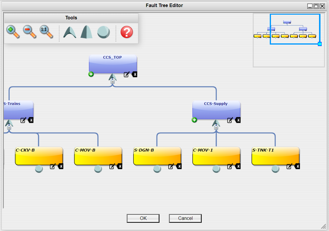
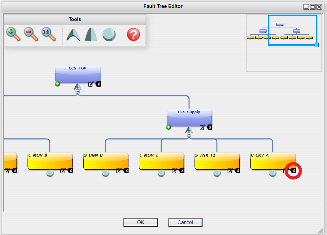
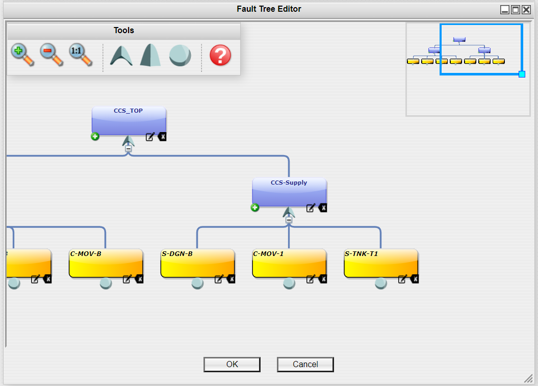
The Fault Tree editor consists of the Tools Window, Navigation Window, and the Editing Area.
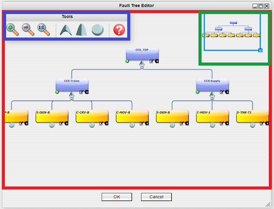 Each section will be explained in detail below.
# Tools Window
Icon | Description |
|---|---|
| Navigation | |
 | Click to zoom in |
 | Click to zoom out |
 | Click to return to actual size |
| Logic Gates | |
 | Drag this icon to add an Or Gate to the Fault Tree |
 | Drag this icon to add an And Gate to the Fault Tree |
 | Drag this icon to add a Basic Event to the Fault Tree |
| Help | |
 | Click to open a basic help document |
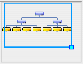
# Navigation Window
The blue rectangle represents the bounds of your current view and the entire Navigation Window is the bounds of your entire logic tree. You can move the blue rectangle around to pan your view. You can also zoom in and out by adjusting the size of the blue rectangle by clicking and dragging the light blue square in the bottom right corner.
# Editing Area
The logic trees consist of two basic elements, Logic Gates (Or and And) and Basic Events. The following sections will explain them in detail and how to model with them.
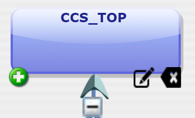
# Logic Gates
Or Gate
And Gate
Adding a Gate
Option 1: From the Tools Window, click and hold on to the gate you would like to add and drag it to the bottom of the desired gate in the Modeling Area until a plus symbol appears then release your mouse.
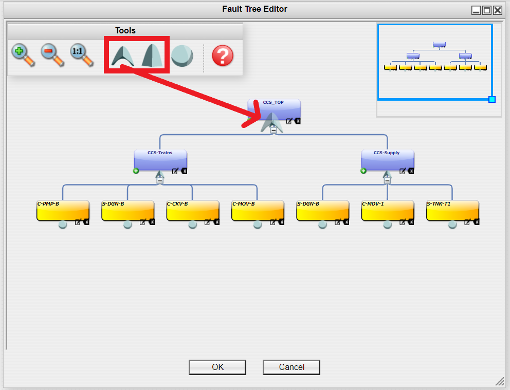
The gate will appear in the Editing Area under the branch you dragged it to.
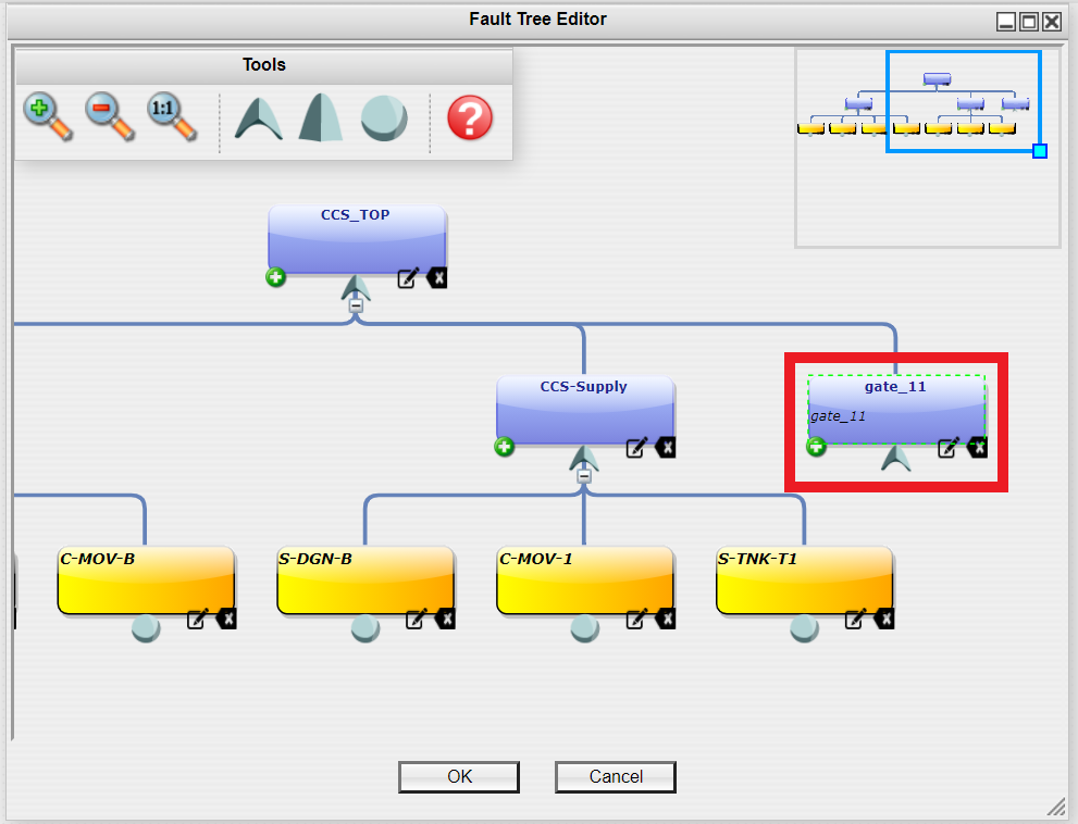
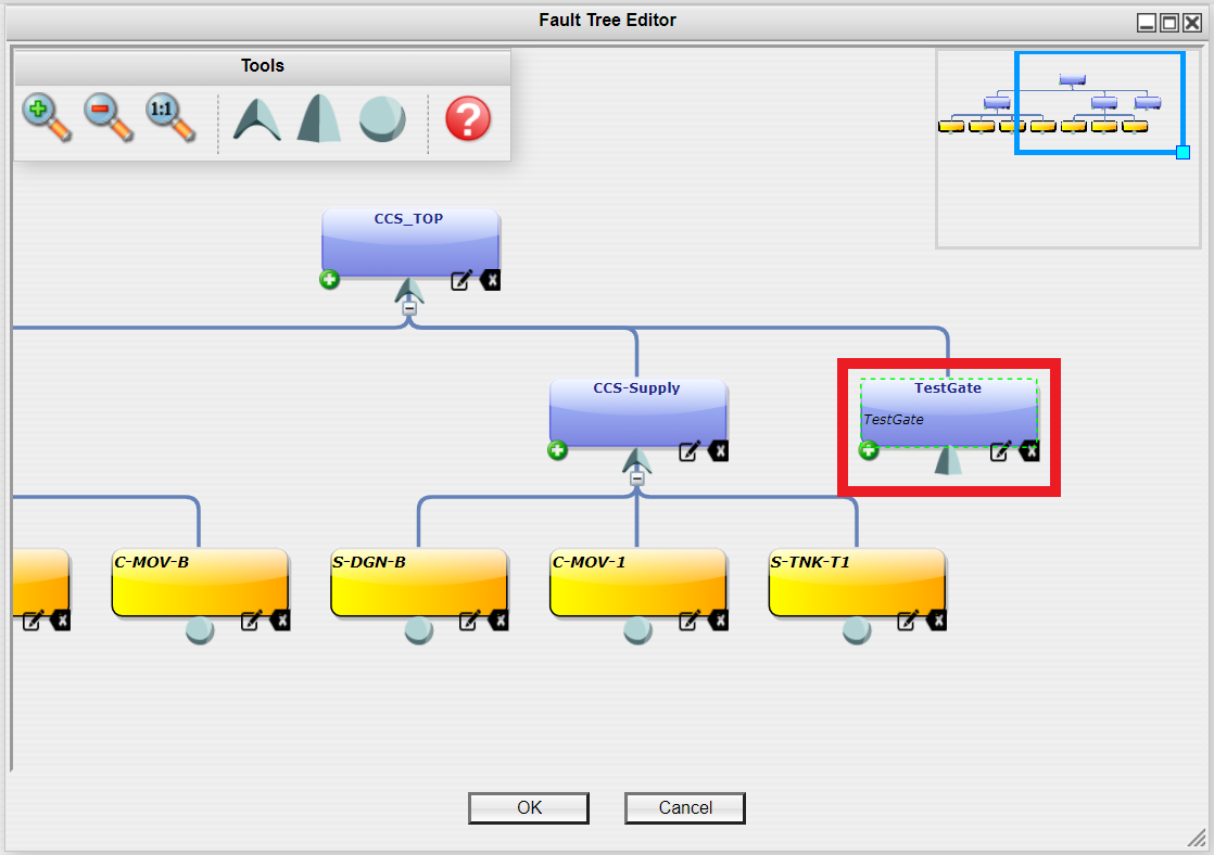
Option 2: In the Editing Area, click on the green circle with the white plus sign in the bottom left corner of the gate you would like to add a new gate under.
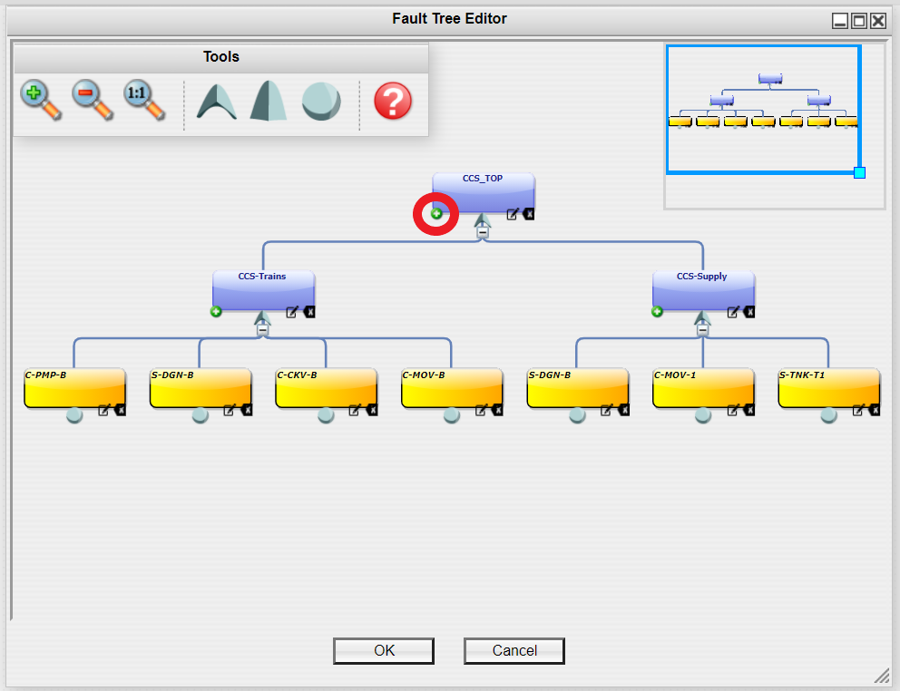
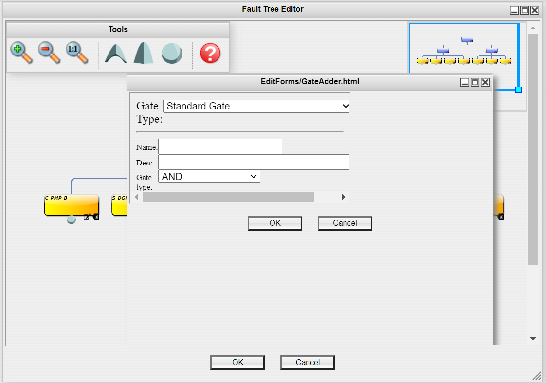
A Edit Forms/Gate Adder window will appear. Fill it out and click "OK." A description is optional.
The gate will appear in the Editing Area under the branch you added it to.
Editing a Gate
In the bottom right hand corner of the gate you would like to edit, click the left icon of the paper and pencil.
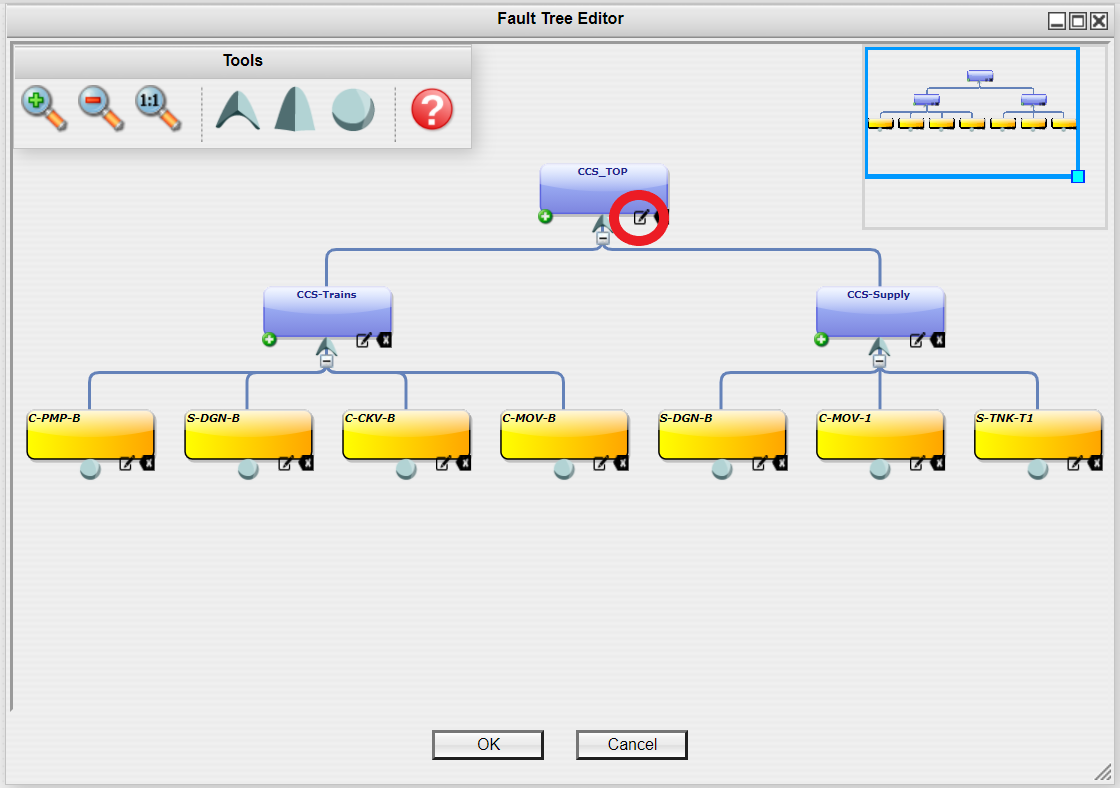
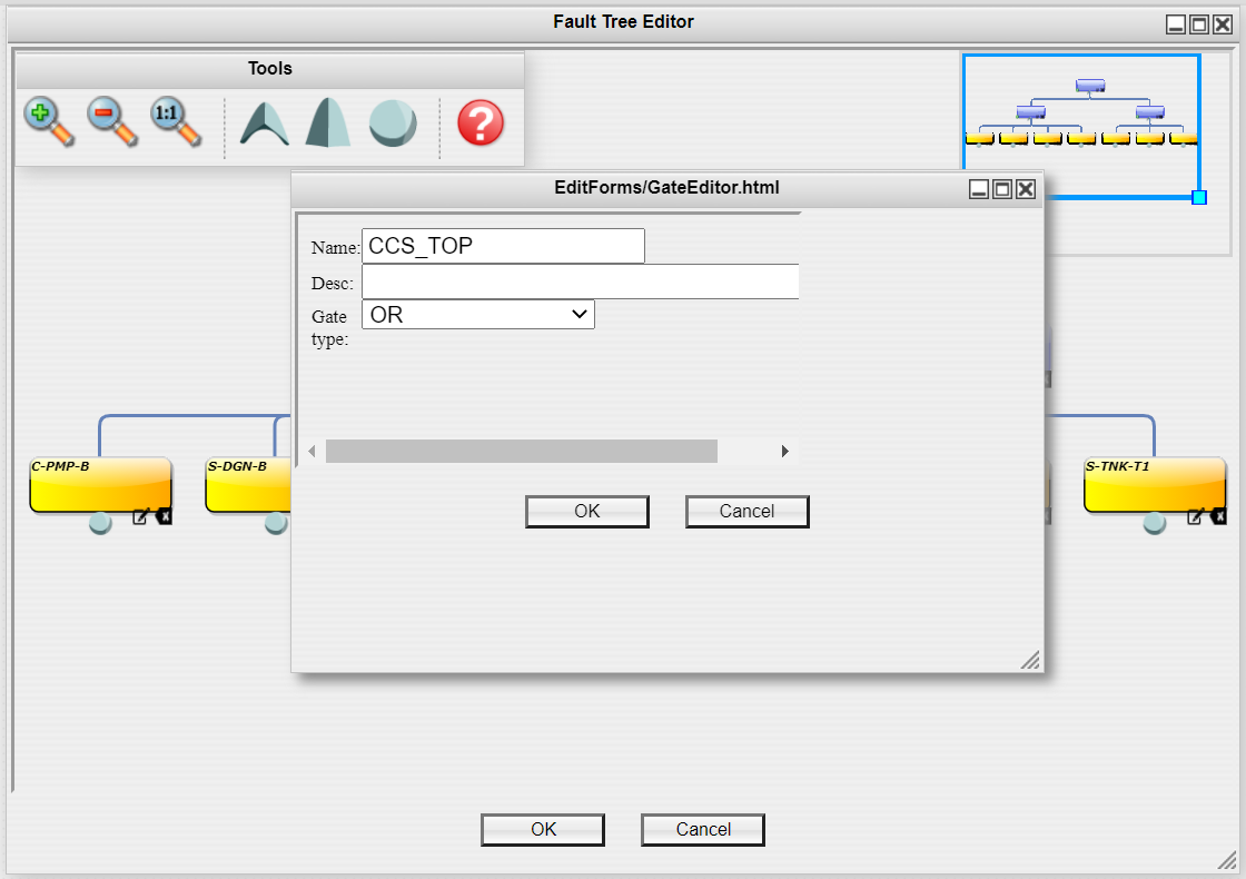
The Edit Forms/Gate Editor window should appear. Click "OK" to confirm the changes.
Deleting a Gate
In the bottom right hand corner of the gate you would like to edit, click the right icon of the backspace symbol. Use caution as no confirmation window will appear.
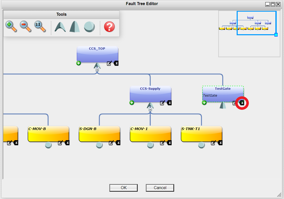
The gate will no longer be shown in the logic tree.
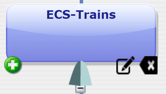
# Basic Events
Adding a Basic Event
Option 1: From the Tools Window, click and hold on to the Basic Event icon and drag it to the bottom of the desired gate in the Modeling Area until a plus symbol appears then release your mouse.
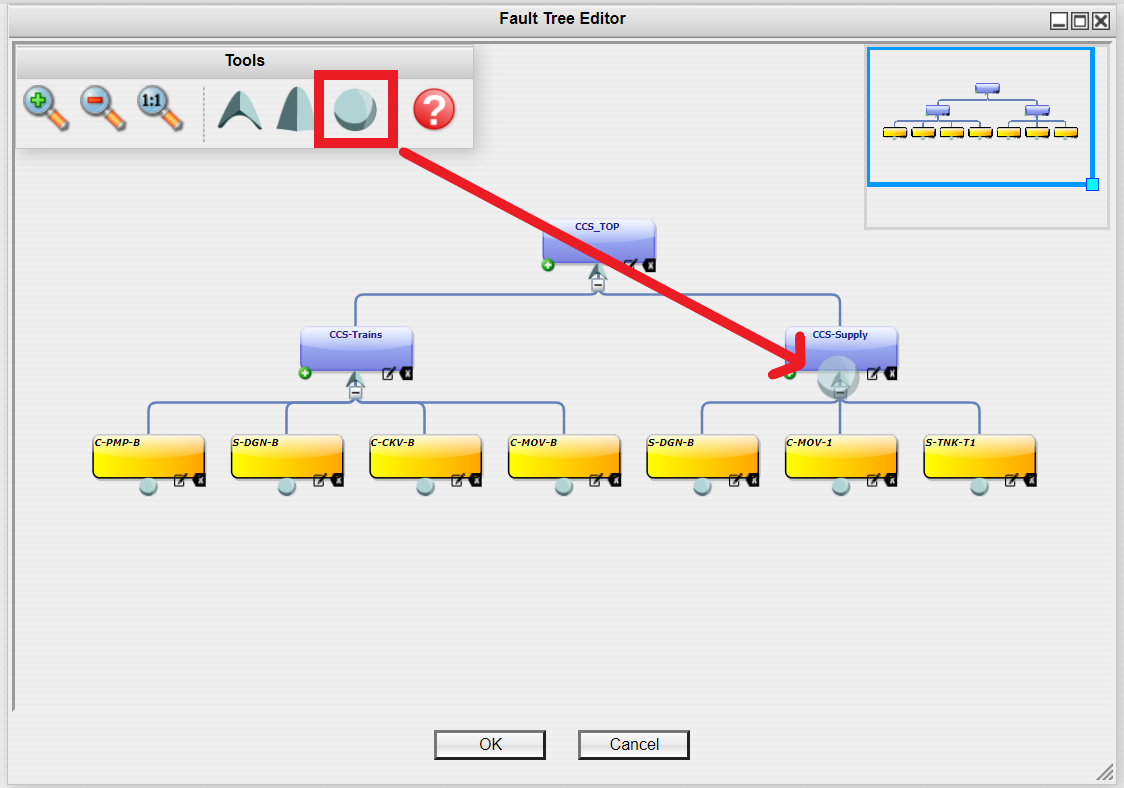
The Edit Forms/Component Adder window will appear. Select the Component Element from the dropdown list and click "OK."
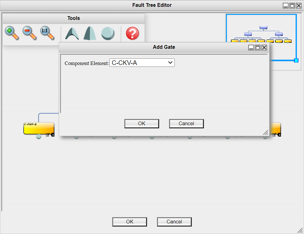
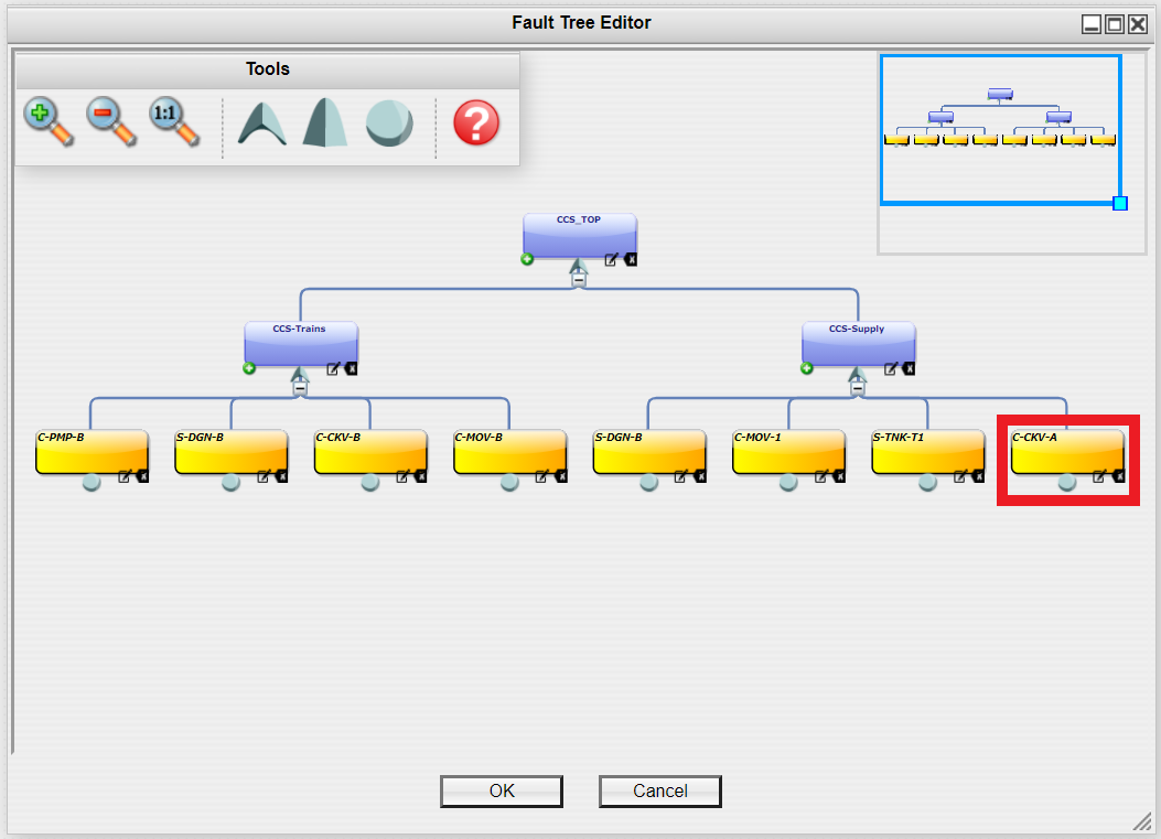
The Basic Event will appear in the Editing Area under the branch you added it to.
Option 2:
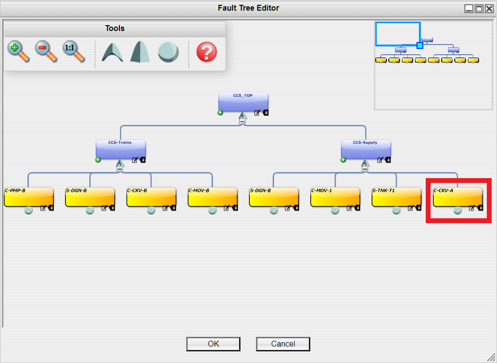
From the Left Navigation Frame, Expand the Diagrams section and the Components folder. Click and hold on the component that you would like to add as a Basic Event to your logic tree and drag it to the Gate you would like it to be under until you see a white plus symbol and release your mouse.
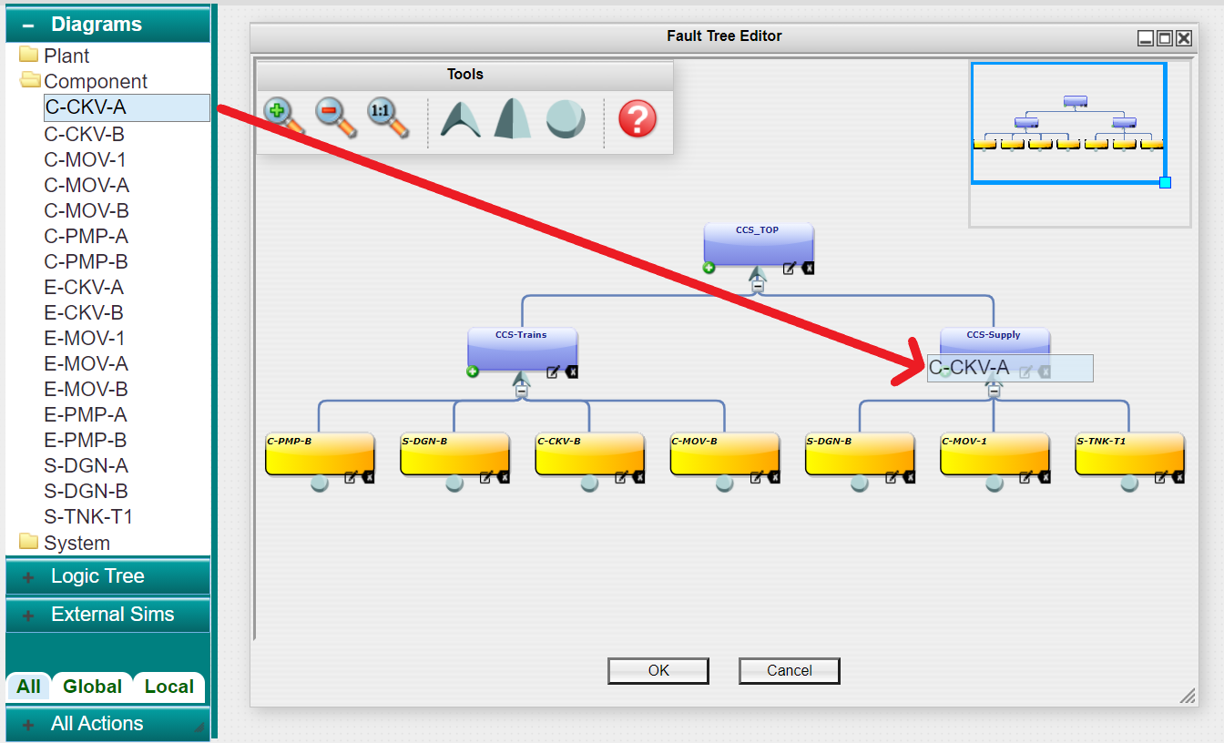
The Basic Event will appear in the Editing Area under the branch you added it to.
Editing a Basic Event
In the bottom right hand corner of the gate you would like to edit, click the left icon of the paper and pencil.
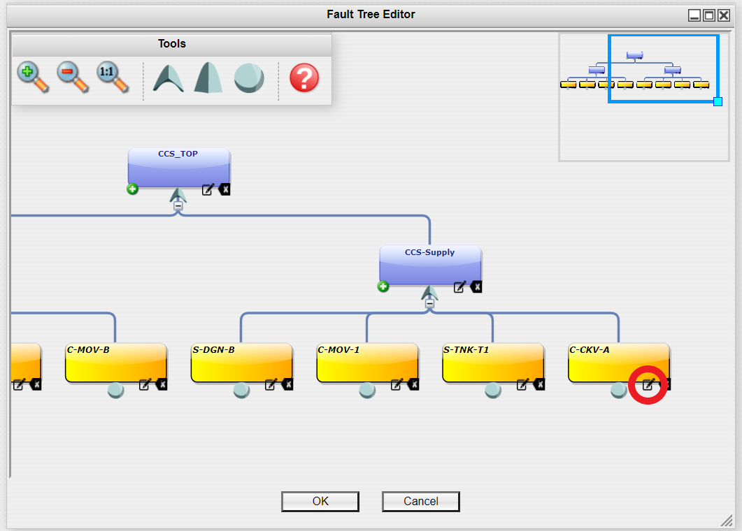
The Diagram window for that component will open in the Modeling Area. You can edit the Component Diagram from this window.
Deleting a Basic Event
In the bottom right hand corner of the Basic Event you would like to edit, click the right icon of the backspace symbol. Use caution as no confirmation window will appear.
The Basic Event will no longer be shown in the logic tree.
# Summary of Shared Symbols
Icon | Description |
|---|---|
 | Click to add a new Logic Gate |
 | Click to edit the element |
 | Click to delete the element |
 | Click to collapse the branches below the gate |
 | Click to expand the branches below the gate |